![]()
THine Value Explaining the Three Benefits of LVDS-equipped LED Driver ICs—Including Resistance to Common Mode Noise and High Design Flexibility
2020.10.21
- Article
- Column
More splendid, more vivid, more striking... Currently, amusement devices and arcade game machines have undergone significant evolution compared to the past.
Why have they been able to evolve in this way? Of course, the biggest reason is user demand. Product planning advanced in response to user feedback. However, that's not the only reason. There are also technical reasons, namely the increase in brightness and reduction in the cost of light-emitting diodes (LEDs). With high-brightness LEDs, fewer LEDs can provide for a brighter display. Additionally, the cost reduction has allowed for the use of more LEDs. Thus, the display functions of amusement devices and arcade game machines have significantly evolved due to the synergy of increased brightness and reduced cost of LEDs.
Why have they been able to evolve in this way? Of course, the biggest reason is user demand. Product planning advanced in response to user feedback. However, that's not the only reason. There are also technical reasons, namely the increase in brightness and reduction in the cost of light-emitting diodes (LEDs). With high-brightness LEDs, fewer LEDs can provide for a brighter display. Additionally, the cost reduction has allowed for the use of more LEDs. Thus, the display functions of amusement devices and arcade game machines have significantly evolved due to the synergy of increased brightness and reduced cost of LEDs.
Poor Noise Environment
Installing numerous LEDs in amusement devices and arcade game machines enables more splendid, more vivid, and more striking display effects. This benefit is significant for equipment manufacturers.
However, the design of the LED driver circuit that drives the LEDs becomes more challenging. This is because the interior of amusement machines and arcade game machines generally have a poor noise environment. These devices contain various high-performance LSIs and high-speed interfaces, which emit high levels of electromagnetic interference (EMI), or noise. Additionally, noise can be generated from contact with medals and other objects. When such noise infiltrates the LED driver circuit, it can cause incorrect LED lighting, resulting in a distorted display that appears unnatural to users.
Why can this noise cause incorrect LED lighting? Let us take a deeper dive into this topic. Generally, in amusement devices and arcade game machines, multiple LED driver ICs are used to drive numerous LEDs. However, there is only one CPU controlling the display. Typically, some form of interface technology is used to connect the CPU with multiple LED driver ICs.
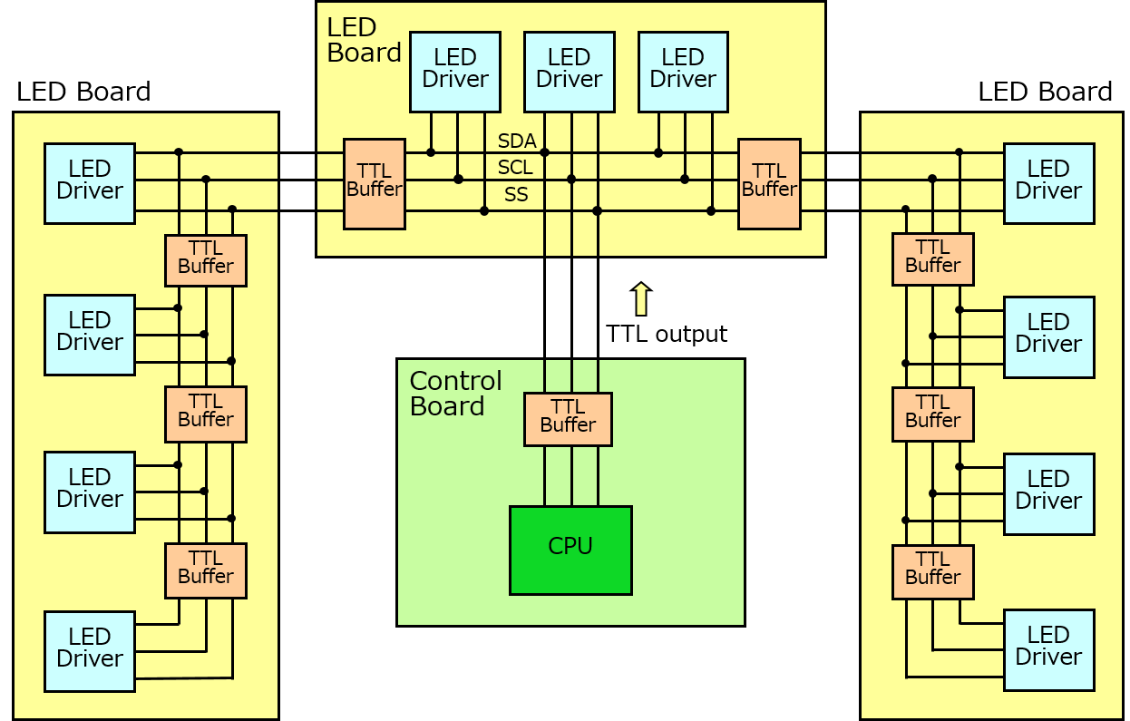
Candidates for this interface technology include the I2C interface method, shift register method, and 3-wire serial interface (2-wire serial interface), with the 3-wire serial interface (2-wire serial interface) being commonly used. The 3-wire interface uses three signal lines to send data (SDA) signals, clock (SCL) signals, and slave select signals (Fig. 1). The 2-wire interface transmits data (SDA) signals and clock (SCL) signals using two signal lines.
When noise infiltrates these serial interfaces, it adversely affects the signals propagating through them. Specifically, the signal waveform becomes distorted, preventing proper signal transmission. There are various paths through which noise can infiltrate. In some cases, noise generated very close by directly enters the serial interface, negatively affecting the signal. In other cases, noise enters the ground, causing the ground potential to fluctuate, which then adversely affects the signals propagating through the serial interface.
In either case, the waveform of the signal propagating through the serial interface becomes severely distorted, preventing correct signal transmission. As a result, LEDs may fail to light up when needed or may light up when not needed.
However, the design of the LED driver circuit that drives the LEDs becomes more challenging. This is because the interior of amusement machines and arcade game machines generally have a poor noise environment. These devices contain various high-performance LSIs and high-speed interfaces, which emit high levels of electromagnetic interference (EMI), or noise. Additionally, noise can be generated from contact with medals and other objects. When such noise infiltrates the LED driver circuit, it can cause incorrect LED lighting, resulting in a distorted display that appears unnatural to users.
Why can this noise cause incorrect LED lighting? Let us take a deeper dive into this topic. Generally, in amusement devices and arcade game machines, multiple LED driver ICs are used to drive numerous LEDs. However, there is only one CPU controlling the display. Typically, some form of interface technology is used to connect the CPU with multiple LED driver ICs.
Candidates for this interface technology include the I2C interface method, shift register method, and 3-wire serial interface (2-wire serial interface), with the 3-wire serial interface (2-wire serial interface) being commonly used. The 3-wire interface uses three signal lines to send data (SDA) signals, clock (SCL) signals, and slave select signals (Fig. 1). The 2-wire interface transmits data (SDA) signals and clock (SCL) signals using two signal lines.
Fig. 1 Example of connection for LED driver IC with 3-wire serial interface
When noise infiltrates these serial interfaces, it adversely affects the signals propagating through them. Specifically, the signal waveform becomes distorted, preventing proper signal transmission. There are various paths through which noise can infiltrate. In some cases, noise generated very close by directly enters the serial interface, negatively affecting the signal. In other cases, noise enters the ground, causing the ground potential to fluctuate, which then adversely affects the signals propagating through the serial interface.
In either case, the waveform of the signal propagating through the serial interface becomes severely distorted, preventing correct signal transmission. As a result, LEDs may fail to light up when needed or may light up when not needed.
Resistant to Common Mode Noise
THine Electronics is already selling the THL35XX series of LED driver ICs that can solve these external noise problems (Fig. 2).
The problem was solved by adopting Low Voltage Differential Signaling (LVDS) as the interface technology to connect the CPU and multiple LED driver ICs (Fig. 3)
LVDS uses a low-amplitude differential transmission method. The amplitude is only 350 mV at 100 Ω termination. Signal transmission uses two signal lines, i.e., one pair of signal lines. THine Electronics' LED driver IC features two pairs of LVDS, which are used to send data and clock signals.
LVDS technology is generally considered to have excellent noise characteristics for two reasons. One is that it has low electromagnetic interference (EMI). This is because it uses a low-amplitude differential transmission method. As a result, it minimizes the adverse effects on surrounding electronic circuits and interfaces.
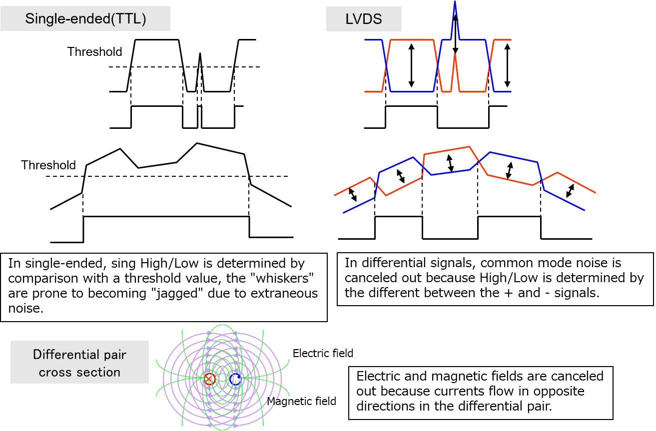
The other is its high resistance to external noise. For example, if external noise enters the ground and causes the ground potential to fluctuate, the same noise is present on the two signal lines that make up a pair. However, since LVDS uses a differential transmission method, the receiving circuit calculates the difference between the two signals. At this point, the noise components cancel each other out, making it less susceptible to external noise (Fig. 4).
Generally, noise caused by fluctuations in ground potential or power supply is called common noise. Thus, LVDS is exceptionally resistant to common mode noise (however, in some cases where external noise is difficult to deal with, it is necessary to adapt to the equipment environment by inserting filter elements, etc.).
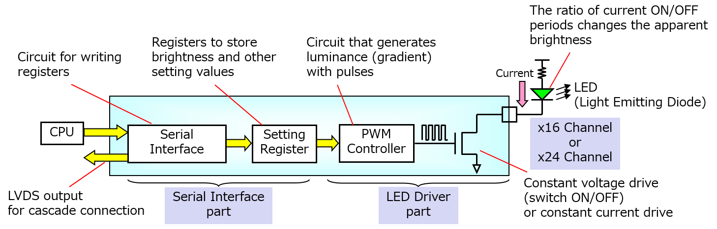
Fig. 2 Simplified block diagram of LED driver IC with LVDS
The problem was solved by adopting Low Voltage Differential Signaling (LVDS) as the interface technology to connect the CPU and multiple LED driver ICs (Fig. 3)
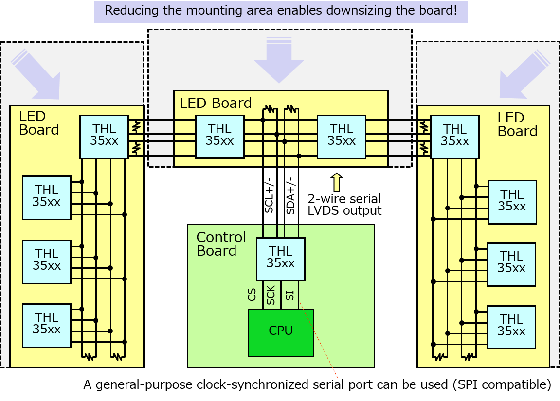
Fig. 3 Example of connection for LED driver IC with LVDS
LVDS uses a low-amplitude differential transmission method. The amplitude is only 350 mV at 100 Ω termination. Signal transmission uses two signal lines, i.e., one pair of signal lines. THine Electronics' LED driver IC features two pairs of LVDS, which are used to send data and clock signals.
LVDS technology is generally considered to have excellent noise characteristics for two reasons. One is that it has low electromagnetic interference (EMI). This is because it uses a low-amplitude differential transmission method. As a result, it minimizes the adverse effects on surrounding electronic circuits and interfaces.
The other is its high resistance to external noise. For example, if external noise enters the ground and causes the ground potential to fluctuate, the same noise is present on the two signal lines that make up a pair. However, since LVDS uses a differential transmission method, the receiving circuit calculates the difference between the two signals. At this point, the noise components cancel each other out, making it less susceptible to external noise (Fig. 4).
Fig. 4 Reasons for the high noise characteristics of LVDS
Generally, noise caused by fluctuations in ground potential or power supply is called common noise. Thus, LVDS is exceptionally resistant to common mode noise (however, in some cases where external noise is difficult to deal with, it is necessary to adapt to the equipment environment by inserting filter elements, etc.).
Mixing Cascades and Multi-drops
LED driver ICs equipped with LVDS have another significant feature. That is the very high design flexibility in the method of connecting LED driver ICs.
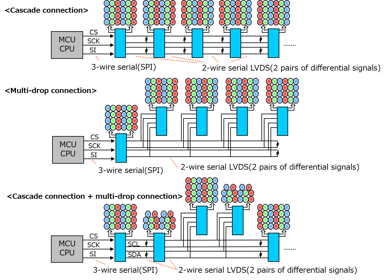
As mentioned earlier, amusement devices and arcade game machines require the driving of numerous LEDs, so multiple LED driver ICs are used. There is only one CPU to control the display. Therefore, the CPU and multiple LED driver ICs must be connected. There are two connection methods: cascade and multi-drop.
The cascade method is what is commonly referred to as daisy chaining. One LED driver IC is connected to the subsequent stage of an LED driver IC, and another LED driver IC is connected to its subsequent stage. In this way, multiple LED driver ICs can be connected in a daisy chain to one LVDS interface.
The multi-drop method, on the other hand, is a method of connecting multiple LED driver ICs hanging on one LVDS interface. In other words, a stub (branch) is set up on the LVDS interface, and the LED driver IC is connected to the end of that branch.
THine Electronics' LED driver ICs support both the cascade and multi-drop methods (Fig. 5). Moreover, the methods can be mixed together. The cascade and multi-drop methods have their own advantages and disadvantages. The cascade method has a simple structure but is difficult to meander or branch off significantly. The multi-drop method can be branched easily, but it requires more wiring, and the mounting area can become relatively large.
Both connection methods can be used appropriately by THine Electronics' LED driver ICs. This is particularly effective in amusement devices when configuring "mechanisms." "Mechanisms" are movable parts that rotate or slide. A small printed circuit board is embedded in these kinds of parts, and an LED driver IC is mounted to drive the LEDs attached to the movable part. It is difficult to connect this LED drive IC in a cascade manner because the LVDS interface cannot be constructed in a straight line. Therefore, a branch can be provided and connected using the multi-drop method.
As mentioned earlier, amusement devices and arcade game machines require the driving of numerous LEDs, so multiple LED driver ICs are used. There is only one CPU to control the display. Therefore, the CPU and multiple LED driver ICs must be connected. There are two connection methods: cascade and multi-drop.
The cascade method is what is commonly referred to as daisy chaining. One LED driver IC is connected to the subsequent stage of an LED driver IC, and another LED driver IC is connected to its subsequent stage. In this way, multiple LED driver ICs can be connected in a daisy chain to one LVDS interface.
The multi-drop method, on the other hand, is a method of connecting multiple LED driver ICs hanging on one LVDS interface. In other words, a stub (branch) is set up on the LVDS interface, and the LED driver IC is connected to the end of that branch.
THine Electronics' LED driver ICs support both the cascade and multi-drop methods (Fig. 5). Moreover, the methods can be mixed together. The cascade and multi-drop methods have their own advantages and disadvantages. The cascade method has a simple structure but is difficult to meander or branch off significantly. The multi-drop method can be branched easily, but it requires more wiring, and the mounting area can become relatively large.
Fig. 5 Cascade and multi-drop methods
Both connection methods can be used appropriately by THine Electronics' LED driver ICs. This is particularly effective in amusement devices when configuring "mechanisms." "Mechanisms" are movable parts that rotate or slide. A small printed circuit board is embedded in these kinds of parts, and an LED driver IC is mounted to drive the LEDs attached to the movable part. It is difficult to connect this LED drive IC in a cascade manner because the LVDS interface cannot be constructed in a straight line. Therefore, a branch can be provided and connected using the multi-drop method.
No Buffer ICs Required
THine Electronics' LED driver ICs have another noteworthy feature.
They have a built-in LVDS repeater function.
Conventionally, when a 2-wire or 3-wire serial interface is adopted, as the connection distance increases, the distortion of the signal waveform and the decrease in amplitude increase, making it more likely that data/clock signals cannot be transmitted correctly, therefore, it was necessary to insert a TTL buffer IC at the entrance of the printed circuit board.
However, THine Electronics' LED driver ICs have a built-in LVDS repeater function. The repeater function receives the LVDS signal, absorbs skew and jitter generated in the signal line or cable, reshapes it into an ideal state on both the voltage and time axes, and then retransmits the LVDS signal. Therefore, the external buffer IC is no longer needed, which reduces the mounting area and cost of the printed circuit board.
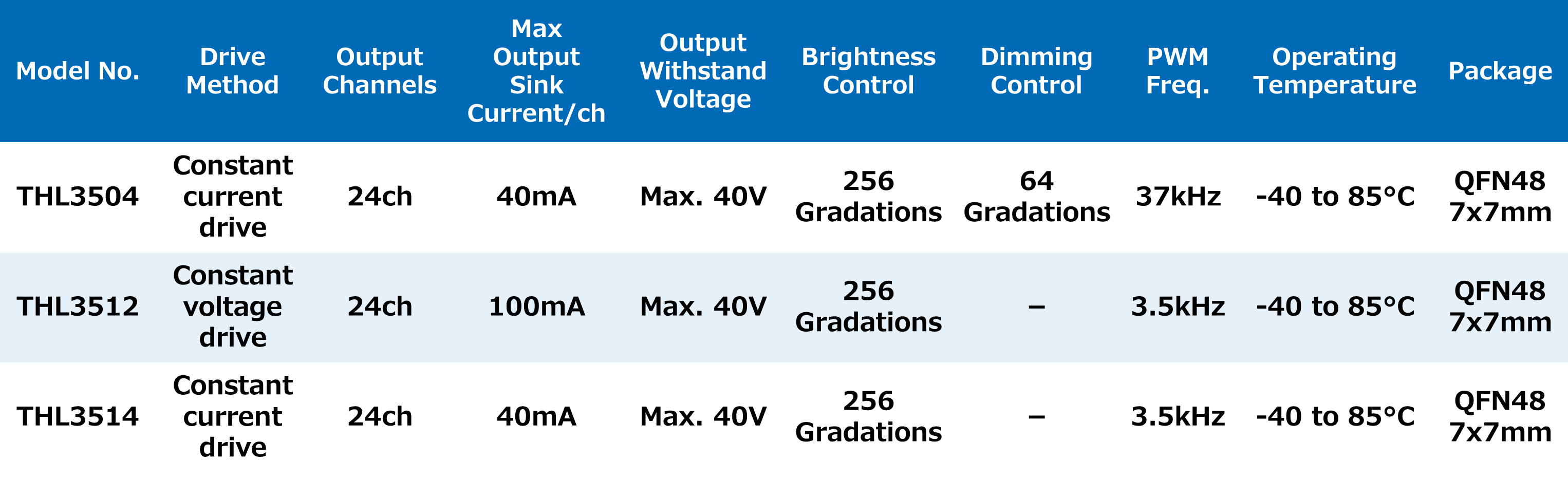
THine Electronics' driver ICs have 24 output channels, and there are a total of three products in the lineup with differences in the driving method (constant voltage drive/constant current drive) and PWM signal frequency (Table 1). The PWM signal frequencies are 37 kHz and 3.5 kHz, and the 3.5 kHz product (THL3512/THL3514) can keep EMI lower.
They have a built-in LVDS repeater function.
Conventionally, when a 2-wire or 3-wire serial interface is adopted, as the connection distance increases, the distortion of the signal waveform and the decrease in amplitude increase, making it more likely that data/clock signals cannot be transmitted correctly, therefore, it was necessary to insert a TTL buffer IC at the entrance of the printed circuit board.
However, THine Electronics' LED driver ICs have a built-in LVDS repeater function. The repeater function receives the LVDS signal, absorbs skew and jitter generated in the signal line or cable, reshapes it into an ideal state on both the voltage and time axes, and then retransmits the LVDS signal. Therefore, the external buffer IC is no longer needed, which reduces the mounting area and cost of the printed circuit board.
THine Electronics' driver ICs have 24 output channels, and there are a total of three products in the lineup with differences in the driving method (constant voltage drive/constant current drive) and PWM signal frequency (Table 1). The PWM signal frequencies are 37 kHz and 3.5 kHz, and the 3.5 kHz product (THL3512/THL3514) can keep EMI lower.
Table 1 Product lineup