![]()
THine Value Achieving Optimization for Touch Panel Devices with the V-by-One HS II SerDes Chipset
2024.11.08
- Article
- Solution
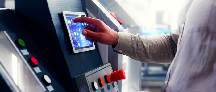
Touch panels have become a common feature in everyday life, driven by the widespread adoption of smartphones and tablets. Their applications continue to expand, and they are now standard components in automotive systems, industrial devices, and POS terminals.

A wide variety of semiconductor chips and electronic components are being commercialized to incorporate touch panels into these various electronic devices. These enable the smooth design and development of touch panel-equipped electronics, minimizing potential issues.
However, semiconductor and electronic component manufacturers are constantly striving to improve performance and functionality, aiming to enhance design efficiency, reduce costs, and boost performance.
To date, THine has developed various SerDes chipsets using V-by-One HS technology specifically for touch panel devices. We have led this development with the aim of extending the transmission range of image signal interfaces. Generally, image signals output from graphics processors (system LSIs) use formats such as OpenLDI (LVDS) or MIPI DSI. The transmission distances for these formats are typically limited to around one meter for the former and 30 centimeters for the latter. For larger electronic devices, the internal connections alone can easily exceed one meter. To address this, SerDes chipsets convert OpenLDI or MIPI DSI signals into V-by-One HS signals for image transmission. This allows signal transmission over distances of up to 15 meters, enabling seamless connections between the graphics processor and touch panel (display), even in larger electronic devices.
Compatible with OpenLDI and MIPI DSI
THine has launched a new SerDes chipset comprising the serializer ICs (transmitting IC, transmitter IC) THCV333-Q/THCV353-Q and the deserializer IC (receiving IC, receiver IC) THCV334-Q. The key feature of the new products is their adoption of V-by-One HS II technology.
The serializer ICs, THCV333-Q and THCV353-Q, differ in the input format of image signals. The THCV333-Q supports OpenLDI (LVDS), while the THCV353-Q supports MIPI DSI (see Figures 1 and 2). On the other hand, the deserializer IC, THCV334-Q, outputs image signals in the OpenLDI (LVDS) format. Typically, serializer ICs and deserializer ICs are used in pairs. The THCV334-Q is compatible with both the THCV333-Q and THCV353-Q.


The forward channel for transmitting image signals achieves a maximum data transfer rate of 3.75 Gbps for the THCV333-Q and 4.00 Gbps for the THCV353-Q. Both models can transmit 720 P, 60 fps, 24-bit image signals as well as 1080 P, 60 fps, 24-bit image signals. Primary applications include touch panel-equipped devices, such as automotive systems, industrial equipment, and POS terminals.
The serializer ICs, THCV333-Q and THCV353-Q, differ in the input format of image signals. The THCV333-Q supports OpenLDI (LVDS), while the THCV353-Q supports MIPI DSI (see Figures 1 and 2). On the other hand, the deserializer IC, THCV334-Q, outputs image signals in the OpenLDI (LVDS) format. Typically, serializer ICs and deserializer ICs are used in pairs. The THCV334-Q is compatible with both the THCV333-Q and THCV353-Q.
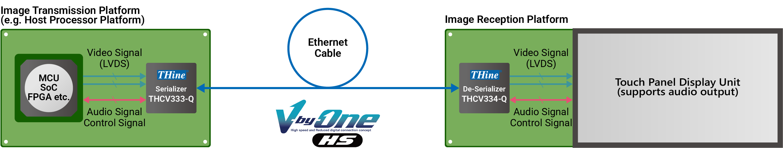
Figure 1 Supporting Image Input in OpenLDI (LVDS) Format
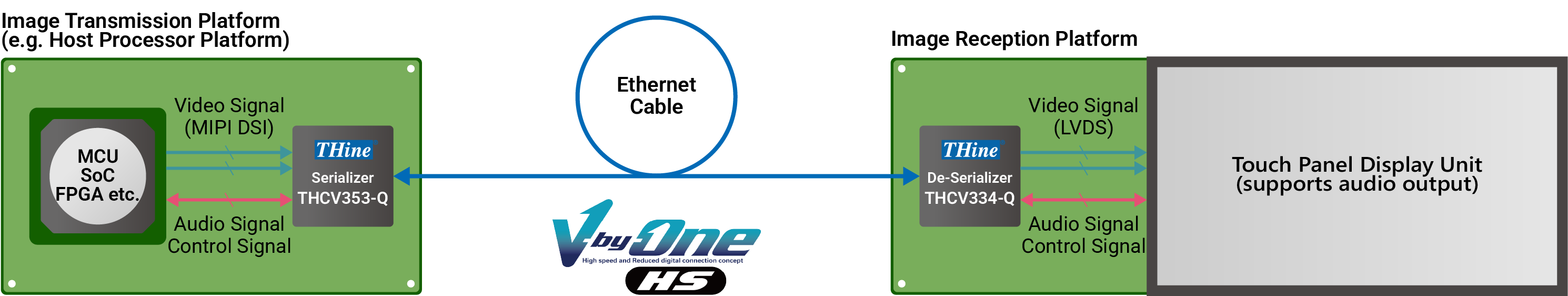
Figure 2 Supports Image Input in MIPI DSI Format
The forward channel for transmitting image signals achieves a maximum data transfer rate of 3.75 Gbps for the THCV333-Q and 4.00 Gbps for the THCV353-Q. Both models can transmit 720 P, 60 fps, 24-bit image signals as well as 1080 P, 60 fps, 24-bit image signals. Primary applications include touch panel-equipped devices, such as automotive systems, industrial equipment, and POS terminals.
Single-Cable Transmission with No External Circuits Required
What advantages do these new products, utilizing V-by-One HS II technology, offer to electronics manufacturers? The biggest benefit is the ability to transmit both image and control signals using a single cable without the need for external superimposition circuits.
Let us dive deeper into this topic. In typical touch panel-equipped electronic devices, various signals must be exchanged between the control unit (serializer IC side) and the touch panel (deserializer IC side). The control unit (serializer IC side) must send image signals to the displayed on the panel (deserializer IC side). In some cases, it also needs to transmit control and audio signals. Conversely, the touch panel (deserializer IC side) must send control signals back to the control unit (serializer IC side) to indicate where the user has touched the panel.
In existing V-by-One HS technology, such signal exchanges were achieved using a main link to transmit image signals from the serializer IC to the deserializer IC and a sub-link to exchange control and audio signals between the two ICs. This required two cables to connect the serializer and deserializer ICs—one for the main link and one for the sub-link. While it is possible to combine control and audio signals with image signals to require only one cable, external superimposition circuits were required.
To address these challenges, V-by-One HS II technology redefined the signal transmission method between the control unit (serializer IC side) and the touch panel (deserializer IC side). Specifically, signals were organized into a unidirectional forward channel from the control unit (serializer IC side) to the touch panel (deserializer IC side) and a unidirectional back channel from the touch panel to the control unit. The forward channel transmits not only image signals but also control and audio signals embedded as packets. Th back channel transmits only control and audio signals.
Only one cable is needed to connect the serializer and deserializer ICs, as both ICSs are equipped with circuits to combine the forward and back channel signals (Figure 3). The forward and back channel signals are transmitted through a single cable by leveraging their differences in transmission frequency. In other words, the forward channel has a maximum data transfer rate of 3.75 Gbps, while the back channel operates at up to 25 Mbps. This significant difference allows the signals to be transmitted through one cable and separated with filter circuits for desired signal reception.
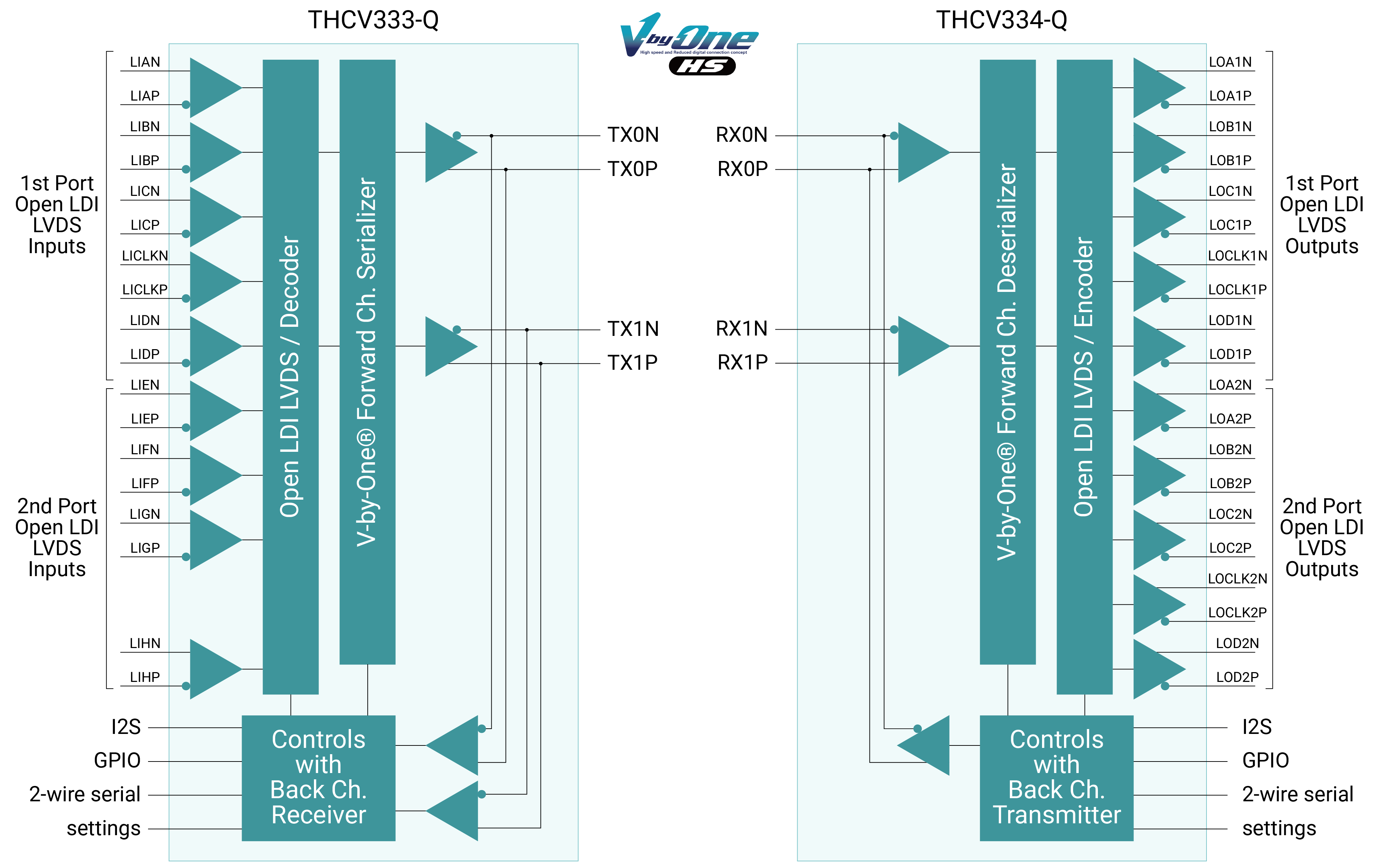
Figure 3 Supports Back Channel Transmission
Equipped with Automatic Transmission Quality Monitoring
Additionally, these new products include features designed further to streamline the development of touch panel-equipped electronic devices.
One such feature is the Eye Monitor function (Signal Transmission Quality Monitor) included in the THCV334-Q deserializer (Figure 4). This functionality is comparable to that found in many high-speed oscilloscopes, but this is the first time our deserializer ICs have included it.

The Eye Monitor feature enables automatic checks to confirm whether high-speed data transmission over the forward channel is functioning correctly. Specifically, the deserializer IC receives data with slightly shifted timing to generate an eye pattern. This pattern is then automatically compared with pre-defined criteria to determine whether it Passes or Fails. The eye pattern can be reviewed using our proprietary development tool, VDesignTool-HSII.
Additionally, the products support a feature called Dual Display. This feature allows for the easy construction of a dual-display system by connecting two THCV334-Q deserializer ICs to a single THCV353-Q serializer IC (Figure 5).

End
One such feature is the Eye Monitor function (Signal Transmission Quality Monitor) included in the THCV334-Q deserializer (Figure 4). This functionality is comparable to that found in many high-speed oscilloscopes, but this is the first time our deserializer ICs have included it.
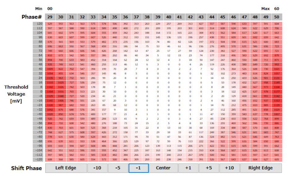
Figure 4 Eye Monitor Feature
The Eye Monitor feature enables automatic checks to confirm whether high-speed data transmission over the forward channel is functioning correctly. Specifically, the deserializer IC receives data with slightly shifted timing to generate an eye pattern. This pattern is then automatically compared with pre-defined criteria to determine whether it Passes or Fails. The eye pattern can be reviewed using our proprietary development tool, VDesignTool-HSII.
Additionally, the products support a feature called Dual Display. This feature allows for the easy construction of a dual-display system by connecting two THCV334-Q deserializer ICs to a single THCV353-Q serializer IC (Figure 5).
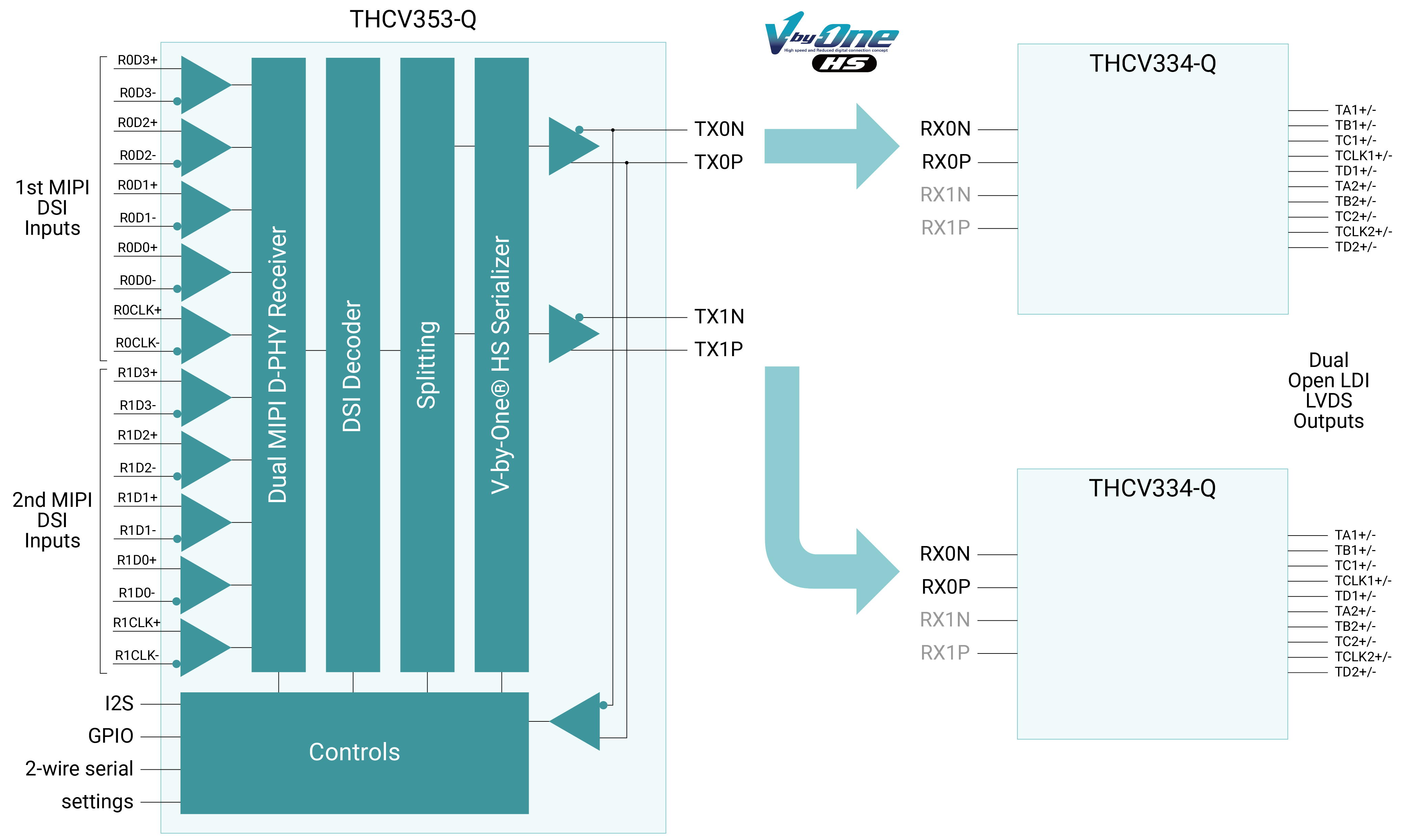
Figure 5 Dual Display Configuration Enabled
End