![]()
THine Value Gigabit speed Redriver IC with equalizer enables longer distance transmission of such high speed interfaces as USB 3.1 Gen2 and HDMI
2020.08.24
- Article
- Column
Peripheral interfaces such as USB, HDMI and DisplayPort are rapidly achieving increases in transfer speed. In the first round of this technical report series that was published last time, we introduced the current state of affairs concerning such ongoing speedup efforts. We also provided a technical explanation of the resulting advantages and disadvantages. In fact, one such disadvantage is proving to be quite a tough nut to crack. This is because the advantage afforded by reducing the maximum data transfer distance could pose a fatal issue depending on the use case. In this second article of the series, we introduce a redriver IC that solves this issue. Using this IC makes it possible to significantly extend the maximum allowable transfer distance.
Culprit is the impedance component of cable
Where such peripheral interfaces as USB, HDMI and DisplayPort are concerned, the higher their transfer rate, the shorter their data-transfer range. Then, why on earth does this phenomenon occur? The cause lies in the impedance of cables that are used to transfer data.
The impedance is dependent on frequency. The higher the frequency, the greater the cable impedance, giving rise to an increased amount of attenuation. As a result, the voltage amplitude of signal waveforms becomes smaller and/or the waveforms become more deformed.
The impedance is dependent on frequency. The higher the frequency, the greater the cable impedance, giving rise to an increased amount of attenuation. As a result, the voltage amplitude of signal waveforms becomes smaller and/or the waveforms become more deformed.
The faster it goes, the higher the attenuation
How great can the attenuation of high-speed signals be when transferred using cables?
As an example, we will consider a case where a USB3.1 Gen2 signal at a maximum data-transmission rate of 10 Gbits/sec. is transferred through an AWG28 coaxial cable measuring 0.3211 mm in diameter over a distance of one meter. The amounts of attenuation recommended by standards for 1.25-GHz, 2.5-GHz and 5.0-GHz signal components are 1.4 dB, 2.0 dB and 3.1 dB, respectively (Fig. 1). In other words, attenuation increases with increasing frequency.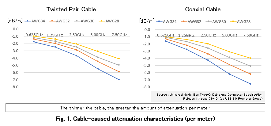
Next, we will replace the cable with a slightly thinner AWG32 coaxial cable measuring 0.2019 mm across for signal transfer purposes. In this case, the amounts of attenuation recommended by standards for 1.25-GHz, 2.5-GHz and 5.0-GHz signal components are 2,2 dB, 3.4 dB and 4.9 dB, respectively. This indicates that the thinner the cable, the greater the amount of attenuation. In other words, the more flexible and easier it is to handle the cable, the greater the amount of attenuation.
More specifically, signal attenuation can be divided into two attenuations. One is the attenuation of DC (low frequency) components, while the other is the attenuation of AC (high frequency) components. The attenuation of DC components is directly linked to the diminishment of signal amplitude. When the signal amplitude becomes too low, the signal cannot be received by the receiver circuit. Conversely, the attenuation of high-frequency components gives rise to a situation where a sufficient opening cannot be obtained in the eye diagram. When the opening diminishes in the eye diagram, the signal cannot be correctly received. Both DC-component attenuation and AC-component attenuation lead to decreases in the maximum allowable transfer distance.
Introducing the Time Linear Equalizer
To cope with the above-mentioned problems, THine Electronics has commercialized the THCX222 Redriver IC.
This IC represents a Continuous Time Linear Equalizer (CTLE) and a driver. By inserting the IC in a peripheral interface in series, it becomes possible to extend the maximum allowable transfer distance.
The linear equalizer (hereinafter, the equalizer) is intended to restore signal components to their original state after undergoing attenuation by the cable (Fig. 2)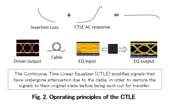
Since the THCX222 amplifies both the DC components and AC components, the gain for both DC and AC components can be set independently. A designer responsible for designing electronic equipment makes attenuation measurements on cables, and sets gain by means of external resistors commensurate with the measurement results (Fig. 3).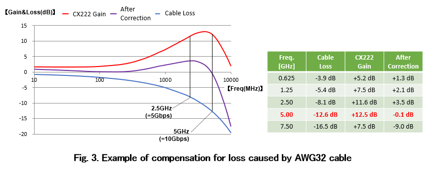
Gain can be set in fine increments. To be more specific, 64 different (6-bit) settings are possible. According to THine Electronics, the THCX222 outperforms comparable products from its competitors in terms of the number of settings that can be made, thus enabling the closest possible optimum settings. The breakdown is as follows: four DC gain settings (2 bits) and eight AC gain settings (3 bits). In the case of the USB 3.1 Gen2-compatible THCX222R10, the maximum values that can be set are +5.2 dB in DC gain and +14.8 dB in AC gain (Fig. 4).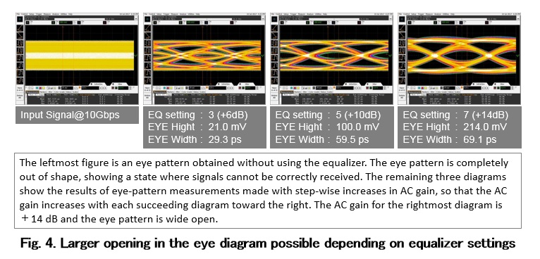
The remaining two different (1 bit) settings are for the sake of output signal linearity. This makes it possible to choose between high and low output signal voltage that would otherwise be saturated (distorted). However, there is a trade-off in that choosing high linearity performance improves transfer performance, but increases power consumption. An appropriate choice should thus be made depending on the application to be adopted.
5-meter extension possible even with a thin cable
We will now cite USB3.1 Gen2 as an example to consider how long the transfer range may be actually extended by using the THCX222.
As was discussed earlier, the data transfer rate of USB3.1 Gen2 is 10 Gbits/sec. However, the maximum frequency component stands at 5 GHz. The THCX222R10 is capable of yielding a gain of +14.8 dB at 5 GHz. In other words, this IC makes it possible to extend the transfer range by the distance corresponding to gain of +14.8 dB.
For example, in the case of an AWG30 coaxial cable measuring 0.2540 mm across, the amount of attenuation recommended by standards at 5.0 GHz is -3.9 dB/m. Therefore, it is possible to extend the transfer range by approximately (14.8 dB/3.9 dB = ) 3.8 m. However, industry standard specifications actually call for the incorporation of provisions for yielding a gain of +6 dB in the receiver circuitry of a USB transceiver IC. By taking this into account, it becomes possible to extend the range by approximately (20.6 dB/3.9 dB = ) 5.3 m. In the case of virtual reality (VR) and augmented reality (AR) terminals, easy cable routing and handling are needed on top of cables 5 m or longer. This requirement can be met through the use of the THCX222 (according to THine Electronics).
As a matter of course, the THCX222 can be used not only for USB but also for HDMI, DisplayPort, and similar interfaces. However, when using the IC with HDMI, note that a capacitor must be connected to the input of the differential interface in order to cut DC components, as well as with a terminator being added.