![]()
THine Value Details of GUI-based tuning tool of Camera Development Kit (CDK) for greatly enhanced ISP performance with no firmware coding
2018.11.29
- Article
- Column
For electronic devices equipped with image sensors, it is essential to use an Image Signal Processor (ISP) that handles image processing and related operations. The development of ISP firmware can be a challenge for such cases. In the first article of this series, we introduced the current situation of ISP firmware development and the proposal by THine Electronics to solve the issues facing such development. By using the “Camera Development Kit (CDK)” offered by THine Electronics, these issues can be solved. In this second article of the series, we will introduce details of the GUI-based tuning tool named “THine Tuning Tool” (commonly known as “3T”), which is one of the components of the CDK. By using the CDK, ISP firmware can be developed without having experience in developing embedded firmware as long as users have knowledge about cameras and image processing.
CDK has a big advantage
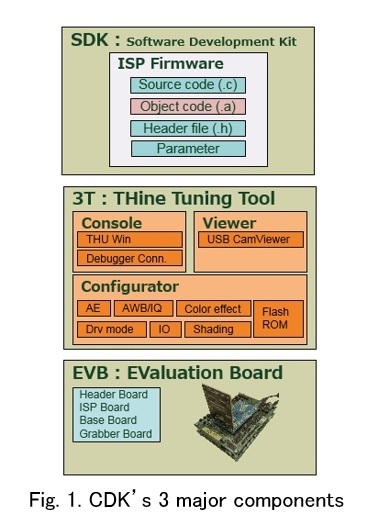 The “Camera Development Kit (CDK)” offered by THine Electronics is aimed at the development of ISP firmware for “THP7312.” In addition to the evaluation board set consisting of a frame grabber board, a board equipped with the ISP chip, and a header board with an image sensor, the kit includes the “Software Development Kit (SDK)” that consists of a firmware library, source code, and a GUI-based tuning tool known as the “THine Tuning Tool (3T)” to customize the SDK, (Fig. 1).
It means that ISP firmware is developed by using three components: (1) the evaluation board (EVB), (2) Software Development Kit, and (3) the GUI-based tuning tool (THine Tuning Tool). According to the development team, “there were ISP chip vendors that provide a software development kit, but there were no vendors that provide a set that includes hardware and a GUI-based tuning tool (*).”
(* At the start of development)
Among these three components, the GUI-based tuning tool offers the greatest advantage for users as firmware can be generated automatically by simply entering numerical values or selecting items from a pull-down menu on a PC with the tool installed. This allows the development cost of firmware to be significantly reduced and the development period shortened. And as long as users have knowledge about cameras, optical technology, and image processing, there is no need to have engineers who specialize in embedded firmware.
The GUI-based tuning tool has more advantages. As firmware can easily be generated in a short period of time, development time can be spent on processes that are essential for the development of cameras, such as repeated experiments/tests on image quality, trials of cameras/modules with different performance, the replacement of optical lenses, and confirmation of effects of infrared (IR) cut filters.
Ten configurators are provided
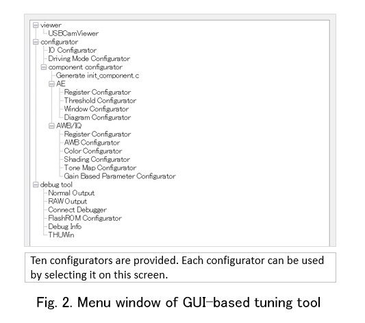
Let's take a closer look at the GUI-based tuning tool “3T” (Fig. 2).
 The main role of the GUI-based tuning tool is the optimization of image quality. As we pointed out in the first article of this series, image sensors output incomplete image data. Therefore, the image data must undergo various types of processing. Configurators are used for this purpose. In the past, program codes for ISP firmware had to be directly written. In contrast, ISP firmware can be generated automatically with simple operations on a PC using the GUI-based tuning tool.
Ten configurators are offered. Let's take a brief look at each one.
The first one is the “AE: Register Configurator.” This configurator handles the adjustment of automatic exposure (auto exposure (AE)), which enables users to configure basic parameters such as the brightness of images and countermeasures for flicker.
The second one is the “AE: Threshold Configurator” (Fig. 3).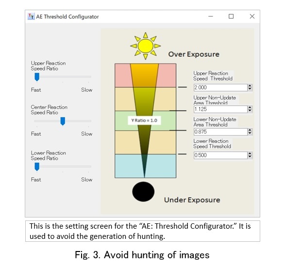 This configurator also handles AE that configures the follow-up for AE to avoid hunting.
The third one is the “AE: Window Configurator.” This one also concerns automatic exposure that achieves AE by combining five types of photometric windows (Fig. 4)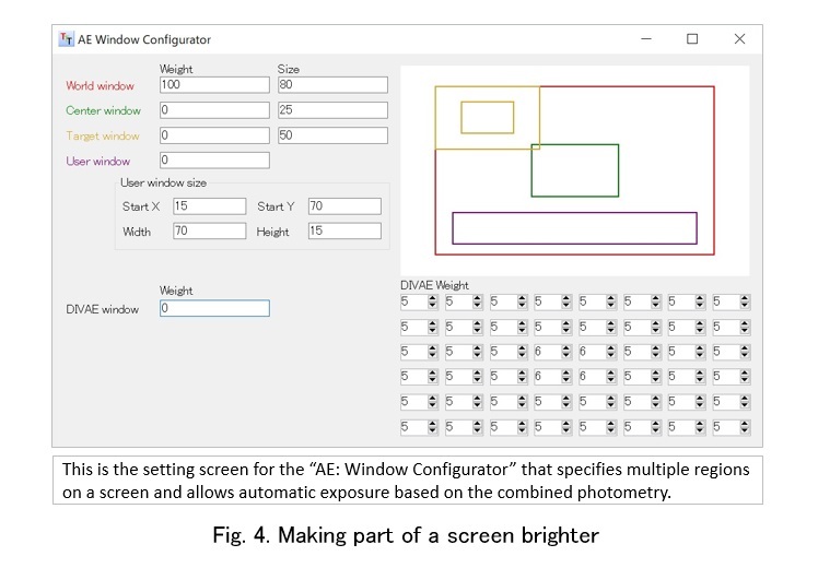 Specifically, one image can be divided into 8 x 6 regions to enable the setting of weighting and performing photometry in the desired regions. For example, images such as a portrait, a setting that emphasizes brightness in the center, can be made.
The fourth one is the “AE: Diagram Configurator.” This configurator sets the gain and shutter speed by using a diagram against the brightness of the subject. There is a trade-off relation between the gain and shutter speed. Increasing the shutter speed reduces camera shake blurring that increases noise as the gain must be increased. Conversely, decreasing the shutter speed to reduce noise makes capturing quick motions difficult. Therefore, selecting only one diagram is difficult depending on the intended use. To handle this issue, this configurator allows the registration of three modes. The image quality priority mode that suppresses noise and the camera shake blurring prevention mode for photographing high-speed subjects can be registered.
The fifth one is the “AWB/IQ: Register Configurator.” This configurator handles settings concerning noise reduction and sharpness. For noise reduction, ISP chips are provided with hardware filters that enable selection of an automatic or manual configuration. The sharpness function allows the degree of emphasis to be specified for the outline of images, thereby enabling such settings as a blurred outline for portraits and a sharp outline for images with many characters. Other than the above-mentioned functions, adjustments including white balance, Tone Map, OB (optical black), and defect correction are also possible.
Ten configurators are offered. Let's take a brief look at each one.
The first one is the “AE: Register Configurator.” This configurator handles the adjustment of automatic exposure (auto exposure (AE)), which enables users to configure basic parameters such as the brightness of images and countermeasures for flicker.
The second one is the “AE: Threshold Configurator” (Fig. 3).
The third one is the “AE: Window Configurator.” This one also concerns automatic exposure that achieves AE by combining five types of photometric windows (Fig. 4)
The fourth one is the “AE: Diagram Configurator.” This configurator sets the gain and shutter speed by using a diagram against the brightness of the subject. There is a trade-off relation between the gain and shutter speed. Increasing the shutter speed reduces camera shake blurring that increases noise as the gain must be increased. Conversely, decreasing the shutter speed to reduce noise makes capturing quick motions difficult. Therefore, selecting only one diagram is difficult depending on the intended use. To handle this issue, this configurator allows the registration of three modes. The image quality priority mode that suppresses noise and the camera shake blurring prevention mode for photographing high-speed subjects can be registered.
The fifth one is the “AWB/IQ: Register Configurator.” This configurator handles settings concerning noise reduction and sharpness. For noise reduction, ISP chips are provided with hardware filters that enable selection of an automatic or manual configuration. The sharpness function allows the degree of emphasis to be specified for the outline of images, thereby enabling such settings as a blurred outline for portraits and a sharp outline for images with many characters. Other than the above-mentioned functions, adjustments including white balance, Tone Map, OB (optical black), and defect correction are also possible.
Offers detailed color adjustment
The sixth one is the “AWB/IQ: AWB Configurator.” It enables taking RAW images on a achromatic chart (such as 18% gray) under three light sources by using the EVB (Evaluation Board), and automatically adjusts white balance parameters.
The seventh one is the “AWB/IQ: Color Configurator.” As the name suggests, this configurator tunes colors and enables the setting of a color matrix for each of the three light sources, as well as the fine adjustment of saturation and hue (Fig. 5)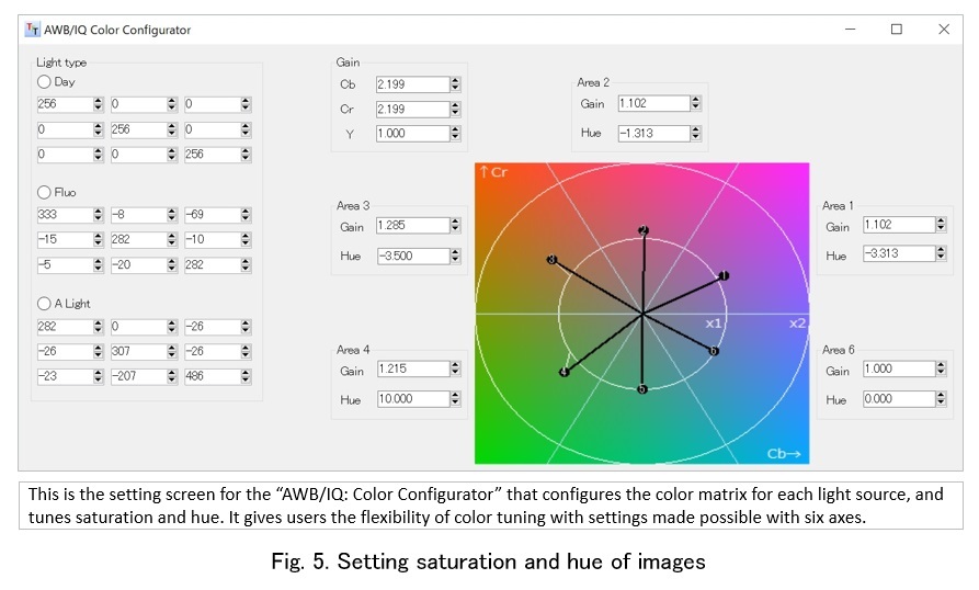 The feature is “fine adjustment with the setting by using six axes” (THine Electronics). It is useful for creating images depending on the purpose of a camera. Photos (in Fig. XX) show examples of image adjustment.
The eighth one is the “AWB/IQ: Shading Configurator.” Generally, when an optical lens is used with an image sensor, the farther it goes from the center, the more difficult it becomes to receive light. Therefore, without any offset, the brightness of images becomes darker going farther from the center. To handle this issue, the lens shading configurator automatically generates appropriate shading parameters for the optical lens to be used by simply entering the achromatic chart’s RAW data under the three light sources input into the AWB configurator. Users are allowed to set the degree of target brightness.
The ninth one is the “AWB/IQ: Tone map Configurator.” This configurator handles adjustment that is generally referred to as gamma correction that specifies output characteristics concerning the gradation of images. Configurations of multiple gamma curves that achieve “the addition of flavor to images” preferred by each user are accepted.
The tenth one is the “AWB/IQ: Gain Based Parameter Configurator.” According to the set gain value, this configurator adjusts the degree of emphasis for saturation and hue in addition to NR (noise reduction) and sharpness. For example, in case of a dark photographing condition with a lot of noise caused by high gain, setting higher NR intensity reduces noise, whereas setting lower NR intensity maintains a spatial resolution.
The seventh one is the “AWB/IQ: Color Configurator.” As the name suggests, this configurator tunes colors and enables the setting of a color matrix for each of the three light sources, as well as the fine adjustment of saturation and hue (Fig. 5)
The eighth one is the “AWB/IQ: Shading Configurator.” Generally, when an optical lens is used with an image sensor, the farther it goes from the center, the more difficult it becomes to receive light. Therefore, without any offset, the brightness of images becomes darker going farther from the center. To handle this issue, the lens shading configurator automatically generates appropriate shading parameters for the optical lens to be used by simply entering the achromatic chart’s RAW data under the three light sources input into the AWB configurator. Users are allowed to set the degree of target brightness.
The ninth one is the “AWB/IQ: Tone map Configurator.” This configurator handles adjustment that is generally referred to as gamma correction that specifies output characteristics concerning the gradation of images. Configurations of multiple gamma curves that achieve “the addition of flavor to images” preferred by each user are accepted.
The tenth one is the “AWB/IQ: Gain Based Parameter Configurator.” According to the set gain value, this configurator adjusts the degree of emphasis for saturation and hue in addition to NR (noise reduction) and sharpness. For example, in case of a dark photographing condition with a lot of noise caused by high gain, setting higher NR intensity reduces noise, whereas setting lower NR intensity maintains a spatial resolution.
How to use configurators
Let's take two examples for different applications to show possible settings with these ten configurators.
The first example is related to industrial machine vision. This example considers the case of testing the implementation status of the upper-left LSI and lower-right LSI mounted on a control board. If these two LSIs are made of different materials, matching the exposure to one of them leads to over or under exposure of the other. In such a case, use the thirdconfigurator (“AE: Window Configurator”) introduced in this article. First, take images with the exposure that matches the upper-left LSI, and then take images with the exposure that matches the lower-right LSI. With this process, clear images can be obtained for the required sections and errorless tests can be performed.
The other example concerns digital mirror stands and beauty cameras. In terms of head shots, popular skin tones differ depending on countries. To satisfy the preferences of various users, the “Color Configurator,” the seventhconfigurator introduced above, can be used. Thus, “image creation” in this way can enhance the commercial value of digital cameras.
Convenient functions including I/O setting
In addition to the above-mentioned ten configurators for image quality adjustment, the GUI-based tuning tool provides two other convenient functions: the I/O configurator and the Driving Mode Configurator.
The I/O configurator handles the input/output signal setting for ISP chips (Fig. 6)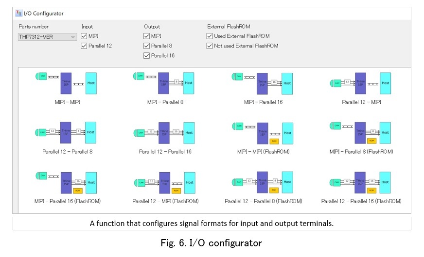 ISP chips have two input interfaces that allow input with MIPI CSI-2 signals or parallel signals, and three output interfaces are provided to support MIPI CSI-2 signals, 8-bit parallel signals, and 16-bit parallel signals. Therefore, the functions of I/O terminals should be configured according to the signal format selected for the device at a preceding stage and the device at a subsequent stage. This setting can easily be made on a PC with the I/O configurator.
The Driving Mode Configurator provides functions to automatically set the clock frequency in the ISP chip and the bit rate for the interface according to the image size and frame rate of the image sensor. “THP 7312” can support up to 16 million pixels (16M pixels). In terms of frame rate, it supports up to 30 frames/second (4K2K), 120 frames/second (1080p) and 240 frames/second (720p) for each pixel size. Selecting the pixel size and frame rate automatically sets the clock frequency in the ISP chip. Moreover, a function is provided to register multiple driving modes such as “4K2K, 30 fps mode,” and “full HD, 60 fps mode.”
In this article, we provided a detailed explanation about the configurators provided with the GUI-based tuning tool, THine Tuning Tool (3T). We believe that each configurator demonstrates great effects for such camera applications as machine vision, surveillance cameras, digital still cameras, and others equipped with image sensors. However, many more types of applications can be handled by the GUI-based tuning tool “3T,” which has already implemented functions for “XR compatible equipment.” In the next (third) article of this series, we will describe these functions and introduce next-generation strategies for the Camera Development Kit.
The I/O configurator handles the input/output signal setting for ISP chips (Fig. 6)
The Driving Mode Configurator provides functions to automatically set the clock frequency in the ISP chip and the bit rate for the interface according to the image size and frame rate of the image sensor. “THP 7312” can support up to 16 million pixels (16M pixels). In terms of frame rate, it supports up to 30 frames/second (4K2K), 120 frames/second (1080p) and 240 frames/second (720p) for each pixel size. Selecting the pixel size and frame rate automatically sets the clock frequency in the ISP chip. Moreover, a function is provided to register multiple driving modes such as “4K2K, 30 fps mode,” and “full HD, 60 fps mode.”
In this article, we provided a detailed explanation about the configurators provided with the GUI-based tuning tool, THine Tuning Tool (3T). We believe that each configurator demonstrates great effects for such camera applications as machine vision, surveillance cameras, digital still cameras, and others equipped with image sensors. However, many more types of applications can be handled by the GUI-based tuning tool “3T,” which has already implemented functions for “XR compatible equipment.” In the next (third) article of this series, we will describe these functions and introduce next-generation strategies for the Camera Development Kit.
Related Contents
- A new development environment for camera systems: CDK will solve problems caused by the fusion of cameras and AI
- Establishing a framework that multilaterally supports embedding camera functions into systems to achieve great progress toward realization of “SWARM/IoT of cameras”
- Developed an automatic generation tool for ISP firmware that is no longer dependent on FPGA